
What we observed from a torn down product recovery system of Ferrous Sulfate


This blog post consists of 4 sections

1. Brief on the Ferrous Sulfate Process (in a customer’s plant)

2. Introduction about Ferrous Sulfate and its hydrate state

3. Ferrous Sulfate in the product recovery system and problems it caused

4. Workplace exposure limit of Ferrous Sulfate

Brief on the Ferrous Sulfate Process

The Ferrous Sulfate heptahydrate bulk first goes through a dryer heated by hot air, then is lifted by a basket elevator to a cooling bed cooled by ambient air from the outside of the building. The exhaust airflows from the dryer and the cooling bed go to the same baghouse for product recovery.

The old product recovery system was removed after years in duty and replaced, since the old one couldn’t meet the airflow requirement for the process. The old baghouse was made of carbon steel, while the new one was made of stainless steel which is more suitable for this moist and corrosive situation.

Introduction about Ferrous Sulfate and its hydrate state

Ferrous Sulfate, also known as Iron(II) sulfate, is the sulfate salt of the iron(II) ion. It is most commonly seen as the heptahydrate which forms blue-green crystals (Fig. 1). It is a white anhydrous powder after completely dehydrated. The old name for the iron(II) sulfate is green vitriol.

Fig. 1 Fe SO4·7H2O (Green Vitriol)

Iron(II) sulfate can be found in various states of hydration, and several of these forms exist in nature.


Ferrous Sulfate in the product recovery system and problems it caused

Ferrous Sulfate heptahydrate with moisture from the dryer is sort of “sticky”, and we happened to have taken a picture of a blast gate just above the dryer bed (see Fig. 2). As you can see, its tongue is covered with Ferrous Sulfate facing the airflow.

Fig. 2 “Sticky” Ferrous Sulfate covers the tongue of the blast gate

After years of operation and seemingly no duct cleaning, the material accumulation almost clogged the ducts (Fig. 3). The same problem can be seen on the side inlet of the baghouse (Fig. 4) and the dust outlet of the baghouse hopper (Fig. 5).

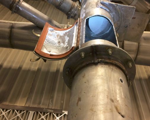
Fig. 3 The Iron Sulfate accumulation inside of a duct

Fig. 4 The Iron Sulfate accumulation inside of the side inlet of the old baghouse

Fig. 5 The Iron Sulfate accumulation around the dust outlet of the old baghouse

Because of the flowability problem of the Ferrous Sulfate with moisture, workers have to occasionally use a hammer to help material discharge from the hopper. Hammer rashes (see Fig. 5) can be seen on the hopper and even on some sections of ductwork.

In dry conditions, Ferrous Sulfate effloresces (see Fig. 6). It seems the efflorescence on the rotor hub is formed by FeSO4·4H2O and/or anhydrous FeSO4  (presumed), which has a white color.

Fig. 6 Efflorescence on the rotor hub of the fan

Upon exposure to (moist) air, Ferrous Sulfate oxidizes to form a corrosive brown-yellow coating of basic ferric sulfate, which is an adduct of ferric oxide and ferric sulfate, because iron(II) compounds are not stable when not kept at a low pH:
12 FeSO4 + 3 O2 → 4 Fe2(SO4)3 + 2 Fe2O3

A brown-yellow coating of basic ferric sulfate (presumed) at the dust outlet of the baghouse hopper (Fig.7) and the same brown-yellow stuff on the floor below the old baghouse (Fig. 8) can be seen.

Fig. 7 Brown-yellow stuff around the dust outlet of the old baghouse hopper

Fig. 8 Brown-yellow powder on the floor below the old baghouse

Both Ferrous Sulfate and Ferric Sulfate are acidic salts.

Ferric Sulfate, a yellow crystalline or grayish-white powder, is corrosive to copper, copper alloys, mild steel, and galvanized steel; it is slightly soluble in water and hygroscopic in air, and forms acidic aqueous solutions.

So, in this application to recover Ferrous Sulfate heptadydrate, corrosive substances have to be taken into consideration as they will damage the filter bags (see Fig. 9).

Fig. 9 Filter bags exposed after cutting a hole on the lower body of the old baghouse

The carbon steel sheets of the baghouse housing were attacked by the corrosive environment inside and also moisture after years in service. The damage is not noticeable from outside. Corroded holes and broken welding points can be seen after the baghouse was taken down (see Fig. 10).


Fig. 10 Broken welding points after the old baghouse laying on the ground

Also, the broken welding line on the fan housing can be clearly seen (Fig. 11), and it’s presumed that it’s caused by the corrosion and the vibration of the fan.


Fig. 11 Broken welding lines on the fan housing

Workplace exposure limit of Ferrous Sulfate

The following exposure limits are for soluble Iron salts (measured as iron):

  • NIOSH: the recommended airborne exposure limit (REL) is 1 mg/m3 averaged over a 10-hour workshift.
  • ACGIH: the threshold limit value (TLV) is 1 mg/m3 averaged over an 8-hour workshift.
A system of local and/or general ventilation system is recommended to keep employee exposures below the Airborne Exposure Limits.


Keywords

Ferrous sulfate, ferric sulfate, green vitriol, FeSO4 7H2O, heptahydrate, product recovery of ferrous sulfate, ferrous sulfate baghouse, acidic sulfate, workplace exposure limit of ferrous sulfate, iron sulfate, Iron(II) sulfate


Comments

Popular posts from this blog

What you have to know when applying blast gate damper

  Introduction A damper is a device that adjusts the volume of airflow passing through the outlet, inlet or duct. By proper adjustment of all dampers in a system, a desired distribution of airflows in all the branches can be obtained, while minimizing the total airflow of the system to save energy— this is also termed air balancing. The most common dampers used in industrial ventilation and dust collection systems to balance airflows are slide gate dampers (The slide gate, also called “blast gate or cut-off” damper). In a slide gate damper (see Figure 1 of a straight flat slide gate damper), the slide is inserted perpendicular to the flow. Figure 1 A sample of straight flat slide gate damper As the gate is sliding into the duct, it will add resistance to the airflow and consequently reduce the volume of airflow, while increasing airflows in all other branches. Withdrawing the gate has the reverse effect on that branch and all the others in a system. Interaction between a fan ...

Push-pull ventilation system for open surface tank saves air flow

  Three sections in this blog: Push-pull ventilation system and its advantages Disadvantages of general ventilation and side exhaust systems Methods to design a push-pull ventilation system Push-pull ventilation system and its advantages Open surface tanks used in industrial processes often need ventilating to remove harmful pollutants (vapors, fumes or aerosols) from the working environment. One method of removing pollutants is the so-called side push-pull ventilation system, in which a jet of air is blown (or pushed) from one side of the tank and collected (or pulled) by an exhaust hood on the opposite parallel side. This system is particularly useful for large tanks where access requirements preclude the use of an overhead canopy, and the size of the tank makes side (or rim) exhaust systems prohibitively expensive. Most agree that a push-pull ventilation system can yield air savings of up to 50% compared to a side suction only hood. An illustration of a push-pull system for an o...

Why and How to do Air Balancing on Industrial Ventilation and Dust Collection Systems?

  Introduction The performances of all the hoods in the whole system normally decide the success of industrial ventilation and dust collection systems from the point of a system owner’s view. The appropriate hood design and its needed airflow rate require the application of good ventilation practice, mastery of the technical knowledge and the ability and patience to do the mathematical calculations. When more than one hood is connected to one ventilation system, the design engineer has to assure that each hood can and will receive the volume of airflow equal or above its designed value and the whole system operates with the minimum possible airflow rate to save energy. This task is termed air balancing of the system or duct balancing. Unbalanced systems cause problems On the contrary, examine the case where one or more hoods are unable to receive desired volume of airflow from an unbalanced ventilation system. It is not uncommon that many hoods are receiving airflow volumes...